Actions


Static calculation of hydraulic drive

Input data:


Number of nodes in the circuit

The    w o r k i n g    f l u i d


Density, kg/m3 Kinematic viscosity, cSt


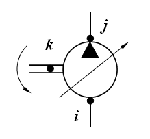
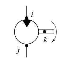
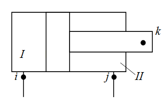
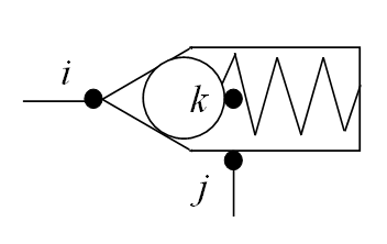
Description of elements of the hydraulic circuit


P u m p s

Number of pumps (to 5)


The pump structural parameters


Physical, geometrical and design parameters of the pump

No

Nodes numbers


Displa-
cement
volume


cm3/rev
Inertia
moment


kg.m2
Gear
ratio
between
diesel
and pump
-
Coef.of
volum.
looses
(leaks)

cm5/(N.s)
Coef.of
hydromech.
looses
depend. on
angul.speed
N.m.s
Coef.of
hydromech.
looses
depend. on
pressure
cm3
Const.
moment of
hydromech.
looses

N.m
Control
range
(for power
regulator)

-
i j k

NOTE: qmin   and   qmax - minimum and maximum displacement volume, control range of pump: 1 - qmin/qmax  _________________________________
           For constant displacement pump its control range is equal to 0.


H y d r a u l i c    m o t o r s

Number of motors (to 5)


The motor structural parameters


Physical, geometrical and design parameters of the motor

No

Nodes numbers


Displa-
cement
volume


cm3/rev
Inertia
moment
reduced
to the
shaft
кг.м2
Gear
ratio
of
working
mechanism
-
Coef.of
volum.
looses
(leaks)

cm5/(N.s)
Coef.of
hydromech.
looses
depend. on
angul.speed
N.m.s
Coef.of
hydromech.
looses
depend. on
pressure
cm3
Const.
moment of
hydromech.
looses

N.m
Control
range
(for power
regulator)

-
i j k

NOTE: qmin и qmax - minimum and maximum displacement volume, control range of motor: qmax/qmin _________________________________________
           For constant displacement hydraulic motor its control range is equal to 1.


H y d r a u l i c    c y l i n d e r s

Number of cylinders (to 5)


The cylinder structural parameters


Physical, geometrical and design parameters of the cylinder

No

Nodes numbers


Mass of
moving
parts
reduced
to rod
kg
Internal
diameter


mm
Rod
diameter
in cavity I
(node i)

mm
Rod
diameter
in cavity II
(node j)

mm
Full
stroke
of
piston

mm
Dry
friction
force in
absence
of pressure
N
Height
of
lip
seal

mm
Coeff.of
viscous
friction


N.s/m
Wall
thickness


mm
Elasticity
module
of wall
material

МPа
i j k


V a l v e s    (of direct action)

Number of valves (to 6)


The valve structural parameters


Physical, geometrical and design parameters of the valve

No

Nodes numbers


Mass of
moving
part


kg
Coeff.of
viscous
friction


N.s/m
Rigi-
dity of
spring


N/m
Preli-
minary
comp-
ression
of spring

mm
Dry
friction
force


N
Working
area
from
pressure
line
(node i)
cm2
Working
area
from
drain
line
(node j)
cm2
Average
diam.
of throt-
tling
crack

mm
Angle
of the
valve
cone


deg
Flow
coeff.
of throt-
tling
crack
-
Maximal
stroke of
moving
part


mm
Area of
parallel
throttle


cm2
Type
of
valve


-
i j k

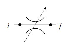
NOTE: Type of valve (latin letters): P - pressure, R - reduction, C - check. _____________________________________________________________________________________

Two-stage   v a l v e s   (of indirect action)

Number of valves (to 3)

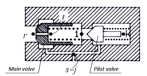
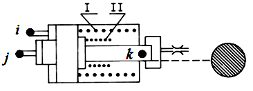
NOTE: The two-stage (of indirect action) valve consists of two moving elements (see Fig.): main valve (nodes r, s, t)
           and pilot valve (nodes i, j, k). At a common drain line of valves: s = j , at separate drain lines: sj .


The main valve structural parameters


Physical, geometrical and design parameters of the main valve

No

Nodes numbers


Mass of
moving
part


kg
Coeff.of
viscous
friction


N.s/m
Rigi-
dity of
spring


N/m
Prelim.
comp-
ression
of spring


mm
Dry
friction
force


N
Working
area
from
pressure
line
(node r)
cm2
Working
area
from
drain
line
(node s)
cm2
Average
diam.
of throt-
tling
crack

mm
Angle
of the
valve
cone


deg
Flow
coeff.
of throt-
tling
crack

-
Maximal
stroke of
moving
part


mm
Diameter
of orifice
aperture


mm
r s t

The pilot valve structural parameters


Physical, geometrical and design parameters of the pilot valve

No

Nodes numbers


Mass of
moving
part


kg
Coeff.of
viscous
friction


N.s/m
Rigi-
dity of
spring


N/m
Prelim.
comp-
ression
of spring


mm
Dry
friction
force


N
Working
area
from
pressure
line
(node i)
cm2
Working
area
from
drain
line
(node j)
cm2
Average
diam.
of throt-
tling
crack

mm
Angle
of the
valve
cone


deg
Flow
coeff.
of throt-
tling
crack

-
Maximal
stroke of
moving
part


mm
i j k


P i p e l i n e s

Number of pipelines (to 25)


The pipeline structural parameters


Physical, geometrical and design parameters of the pipeline

No
Nodes numbers


Internal
diameter


mm
Length


m
Wall
thickness


mm
Elasticity
module
of wall
material
МPа
i j k


D e a d l o c k    s i t e s    of    p i p e l i n e s

Number of deadlock sites (to 5)


The deadlock pipeline structural parameters


Physical, geometrical and design parameters of the deadlock pipeline

No
Nodes numbers


Internal
diameter


mm
Length


m
Wall
thickness


mm
Elasticity
module
of wall
material
МPа
i j k


T h r o t t l e s    (local resistances)

Number of throttles (to 15)


The throttle structural parameters


Physical, geometrical and design parameters of the throttle

No
Nodes numbers


Through
passage
section
area

cm2
Flow
coef-
ficient


-
Coeff.of
hydr.
resis-
tance

-
i j k


T e e s    (dividers or adders of flows)

Number of tees (to 15)


The tee structural parameters


Physical, geometrical and design parameters of the tee

No

Nodes numbers

Diameter
in node i


mm
Diameter
in node j


mm
Diameter
in node k


mm
Coeff.of
local
hydraulic
resistance
i - j
-
Coeff.of
local
hydraulic
resistance
i - k
-
Coeff.of
local
hydraulic
resistance
j - k
-
Sign
of impact
on flows


-
i j k

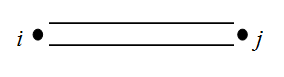
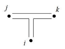
 NOTES: 1. At dividing of flows:  i - an input node, j  and  k - output nodes, sign is D. _______________________________________________
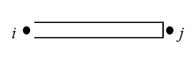
              2. At adding of flows:  i  and  j - input nodes, k - an output node, sign is S.


H y d r a u l i c    a c c u m u l a t o r s

Number of accumulators (to 5)


The accumulator structural parameters


Physical, geometrical and design parameters of the accumulator

No

Nodes numbers


Accumu-
lator
volume


l
Mass of
moving
parts


kg
Piston
diameter


mm
Pressure
of charged
gas


MPa
Exponent
of poly-
tropic
process


-
Maximal
stroke
of piston


mm
Dry
friction
force in
absence
of pressure
N
Height
of the
lip
seal


mm
Rigi-
dity
of
spring


N/m
Prelim.
comp-
ression
of
spring

mm
Coeff.of
viscous
friction


N.s/m
Wall
thickness


mm
Elasticity
module
of wall
material


МPа
i j k
NOTES: 
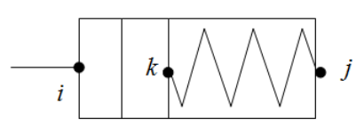
1. For a gas accumulator a rigidity and preliminary compression of spring are equal to 0.
             2. For a spring accumulator a pressure of charged gas and an exponent of polytropic process are equal to 0.


P o w e r    r e g u l a t o r s

Number of regulators (to 5)


The regulator structural parameters


Physical, geometrical and design parameters of the regulator

No


Nodes numbers


Reduced
mass of
turning
part of
pump


kg
Coeff.of
viscous
friction


N.s/m
Rigi-
dity
of
spring I


N/m
Rigi-
dity
of
spring II


N/m
Force
of spring
prelim.
compres-
sion


N
Force
of dry
friction


N
Working
area of
plunger


cm2
Coeff.
taking
into
account
an addit.
unfolding
moment
-
Plunger
stroke
on
branch I


mm
Maximal
plunger
stroke


mm
i j k
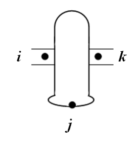
NOTE: If the power regulator is controled by pressure of one node of circuit, then i = j .


W h e e l    m o v e r

Number of wheels (axles) (to 8)


NOTES:
1. This element is either a wheel with independent drive, or the drive axle.
2. Side scheme of transmission is replaced by the equivalent two-wheel scheme with independent drive of wheels.
3. The moment of inertia is given to the shaft of the wheel motor (axis, side) and is shown in the table of motor's data.


The wheel structural parameters


Physical, geometrical and design parameters of the wheel

No

Nodes numbers

Gear
ratio


-
Efficiency
of gear


-
Free
radius
of
wheel

m
Vertical
axle
(wheel)
load

N
Radial
stiffness
of tire


N/m
Circum-
ferential
stiffness
of tire

N/m
Rolling
resistance
coeff.


-
i j k
W h e e l    s l i p p i n g    c u r v e    δ ( R ).
R - circumferential force on the wheel, N;    δ - relative slipping, dimensionless.

R1 R2 R3 R4 R5 R6 R7 R8 R9 R10
δ1 δ2 δ3 δ4 δ5 δ6 δ7 δ8 δ9 δ10


D i e s e l s

Number of diesels (to 2)


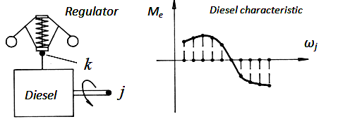
NOTE: If inertia moment of diesel rotating parts is 0, the diesel in the calculation is ignored and
           angular speed of its shaft is assumed fixed, corresponding to the zero approximation.


The diesel structural parameters


Physical, geometrical and design parameters of the diesel

No

Nodes numbers


Inertia
moment
of
rotating
details


kg.m2
Torque
incre-
ment
at max
fuel
supply

N.m
Coeff.of
viscous
friction
in the
diesel
regulator

N.s/m
Coefficients of diesel regulator setting


Gear
ratio
of
regulator
drive


-
Rigidity
of
regulator
spring


N/m
Force
of
regulator
spring
prelimin.
compres-
sion
N
Maximal
stroke
of
regulator
muff


mm

i

j

k
ke

N
b

N.s2
k

N.s2/m
The    d i e s e l    c h a r a c t e r i s t i c    Мe ( ωj ).
ωj - an angular velocity of the diesel shaft (in node j ), rad/s;    Мe - the diesel shaft torque, N.m .

ω1 ω2 ω3 ω4 ω5 ω6 ω7 ω8 ω9 ω10
M1 M2 M3 M4 M5 M6 M7 M8 M9 M10


P a r a m e t e r s    of    the    v e h i c l e    m o t i o n


Minimum traction, N Maximum traction, N Traction force increment (step), N


E x t e r n a l    l o a d s

in order of numbers of hydraulic motors
in order of numbers of hydraulic cylinders


R e l a t i v e    d i s p l a c e m e n t    v o l u m e s    of    h y d r a u l i c    m a c h i n e s

in order of numbers of pumps
in order of numbers of hydraulic motors


N u m b e r s    of    p o w e r    r e g u l a t o r s    of    h y d r a u l i c    m a c h i n e s

in order of numbers of pumps
in order of numbers of hydraulic motors


P a r a m e t e r s    for    c a l c u l a t i o n

0 - the screen sets (see below), 1 - is recorded in file


Z e r o    a p p r o x i m a t i o n


NOTE.  Zero approximation has the following structure: node number - "force" - "speed" - "displacement",
            where "force" - pressure (MPa), force (N) or torque (N.m); "speed" - flow (l/min), linear speed (cm/s) or angular speed (rad/s),
            "displacement" - linear displacement (cm), rotation angle (rad) or slipping (-).


What    n o d e s    of    the    c i r c u i t    the    c a l c u l a t i o n    r e s u l t s    are    d i s p l a y e d


NOTE:
List of the circuit nodes, in which the results set displays in ascending order of node numbers.
If necessary to output all nodes of the circuit, put 0 instead of the list or at the beginning (in this case the list is ignored).
If necessary to output not in all nodes, but in the given nodes, you can specify the list of these nodes, and 0 is not assigned.