Actions


Dynamic analisys of hydraulic drive

Input data:


Number of nodes in the circuit


The    w o r k i n g    f l u i d


Density, kg/m3 Kinematic viscosity, сSt Volumetric module of elasticity, МPа


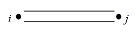
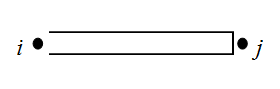
Description of elements of the hydraulic circuit


P u m p s

Number of pumps (to 5)


The pump structural parameters


Physical, geometrical and design parameters of the pump

No

Nodes numbers


Displa-
cement
volume


cm3/rev
Inertia
moment


kg.m2
Gear
ratio
between
diesel
and pump
-
Coef.of
volum.
looses
(leaks)

cm5/(N.s)
Coef.of
hydromech.
looses
depend.on
angul.speed
N.m.s
Coef.of
hydromech.
looses
depend.on
pressure
cm3
Const.
moment of
hydromech.
looses

N.m
i j k


H y d r a u l i c    m o t o r s

Number of motors (to 5)


The motor structural parameters


Physical, geometrical and design parameters of the motor

No

Nodes numbers


Displa-
cement
volume


cm3/rev
Inertia
moment
reduced
to shaft

kg.m2
Gear
ratio
of
working
mechanism
-
Coef.of
volum.
looses
(leaks)

cm5/(N.s)
Coef.of
hydromech.
looses
depend.on
angul.speed
N.m.s
Coef.of
hydromech.
looses
depend.on
pressure
cm3
Const.
moment of
hydromech.
looses

N.m
i j k


H y d r a u l i c    c y l i n d e r s

Number of cylinders (to 5)


The cylinder structural parameters


Physical, geometrical and design parameters of the cylinder

No

Nodes numbers


Mass of
moving
parts
reduced
to rod
kg
Internal
diameter


mm
Rod
diameter
in cavity
I
(node i)
mm
Rod
diameter
in cavity
II
(node j)
mm
Full
stroke
of piston


mm
Dry
friction
force in
absence
of pressure
N
Height
of lip
seal


mm
Coeff.of
viscous
friction


N.s/m
Wall
thickness


mm
Elasticity
module
of wall
material

МPа
i j k


V a l v e s    (of direct action)

Number of valves (to 6)


The valve structural parameters


Physical, geometrical and design parameters of the valve

No

Nodes numbers


Mass of
moving
part


kg
Coeff.of
viscous
friction


N.s/m
Rigi-
dity of
spring


N/m
Prelim.
comp-
ression
of spring

mm
Dry
friction
force


N
Working
area
from
pressure
line
(node i)
cm2
Working
area
from
drain
line
(node j)
cm2
Average
diam.
of throt-
tling
crack

mm
Angle
of the
valve
cone


deg
Flow
coeff.
of throt-
tling
crack
-
Maximal
stroke of
moving
part


mm
Area of
parallel
throttle


cm2
Type
of
valve


-
i j k
NOTE: Type of valve (latin letters): P - pressure, R - reduction, C - check.__________________________________________________________________________


The two-stage    v a l v e s    (of indirect action)

Number of valves (to 3)

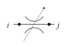
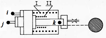
NOTE: The two-stage (indirect action) valve consists of two moving elements (see Fig.): main valve (nodes r, s, t) and
                               pilot valve (nodes i, j, k). At a common drain line of valves: s = j , at separate drain lines: sj .


The main valve structural parameters


Physical, geometrical and design parameters of the main valve

No

Nodes numbers


Mass of
moving
part


kg
Coeff.of
viscous
friction


N.s/m
Rigi-
dity of
spring


N/m
Prelim.
comp-
ression
of spring


mm
Dry
friction
force


N
Working
area
from
pressure
line
(node r)
cm2
Working
area
from
drain
line
(node s)
cm2
Average
diam.
of throt-
tling
crack

mm
Angle
of the
valve
cone


deg
Flow
coeff.
of throt-
tling
crack
-
Maximal
stroke of
moving
part


mm
Diameter
of orifice
aperture


mm
r s t


The pilot valve structural parameters


Physical, geometrical and design parameters of the pilot valve

No

Nodes numbers


Mass of
moving
part


kg
Coeff.of
viscous
friction


N.s/m
Rigi-
dity of
spring


N/m
Prelim.
comp-
ression
of spring


mm
Dry
friction
force


N
Working
area
from
pressure
line
(node i)
cm2
Working
area
from
drain
line
(node j)
cm2
Average
diam.
of throt-
tling
crack

mm
Angle
of the
valve
cone


deg
Flow
coeff.
of throt-
tling
crack
-
Maximal
stroke of
moving
part


mm
i j k


P i p e l i n e s

Number of pipelines (to 25)


The pipeline structural parameters


Physical, geometrical and design parameters of the pipeline

No
Nodes numbers


Internal
diameter


mm
Length


m
Wall
thickness


mm
Elasticity
module
of wall
material
МPа
i j k


D e a d l o c k    s i t e s    of    p i p e l i n e s

Number of deadlock sites (to 5)


The deadlock pipeline structural parameters


Physical, geometrical and design parameters of the deadlock pipeline

No
Nodes numbers


Internal
diameter


mm
Length


m
Wall
thickness


mm
Elasticity
module
of wall
material
МPа
i j k


T h r o t t l e s    (local resistances)

Number of throttles (to 15)


The throttle structural parameters


Physical, geometrical and design parameters of the throttle

No
Nodes numbers


Through
passage
section
area
cm2
Flow
coefficient


-
Coeff.of
hydraulic
resistance

-
i j k


T e e s    (dividers or adders of flows)

Number of tees (to 15)


The tee structural parameters


Physical, geometrical and design parameters of the tee

No

Nodes numbers

Diameter
in node i


mm
Diameter
in node j


mm
Diameter
in node k


mm
Coeff.of
local
hydraulic
resistance
i - j
-
Coeff.of
local
hydraulic
resistance
i - k
-
Coeff.of
local
hydraulic
resistance
j - k
-
Sign
of impact
on flows


-
i j k
 NOTES: 
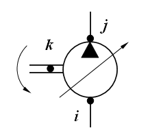
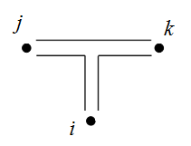
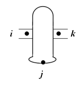
1. At dividing of flows:  i - an input node, j  and  k - output nodes, sign D. __________________________________________________
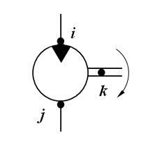
              2. At adding of flows:  i  and  j - input nodes, k - an output node, sign S.


H y d r a u l i c    a c c u m u l a t o r s

Number of accumulators (to 5)


The accumulator structural parameters


Physical, geometrical and design parameters of the accumulator

No

Nodes numbers


Accumu-
lator
volume


l
Mass of
moving
parts


kg
Piston
diameter


mm
Pressure
of charged
gas


MPa
Exponent
of poly-
tropic
process


-
Maximal
stroke
of piston


mm
Dry
friction
force in
absence
of pressure
N
Height
of lip
seal


mm
Rigidity
of
spring


N/m
Prelim.
comp-
ression
of
spring

mm
Coeff.of
viscous
friction


N.s/m
Wall
thickness


mm
Elasticity
module
of wall
material


МPа
i j k

NOTES: 
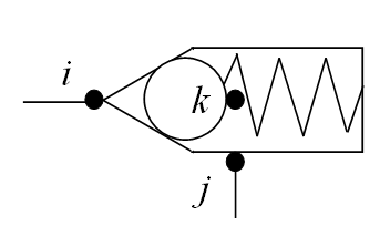
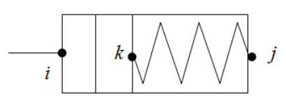
1. For a gas accumulator a rigidity and preliminary compression of spring are equal to 0.
             2. For a spring accumulator a pressure of charged gas and an exponent of polytropic process are equal to 0.
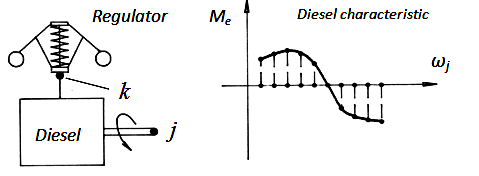

P o w e r    r e g u l a t o r s

Number of regulators (to 5)


The regulator structural parameters


Physical, geometrical and design parameters of the regulator

No


Nodes numbers


Reduced
mass of
turning
part of
pump


kg
Coeff.of
viscous
friction


N.s/m
Rigi-
dity
of
spring
I


N/m
Rigi-
dity
of
spring
II


N/m
Force
of spring
prelim.
compres-
sion


N
Force
of dry
friction


N
Working
area of
plunger


cm2
Coeff.
taking
into
account
an addit.
unfolding
moment
-
Plunger
stroke
on
branch I


mm
Maximal
plunger
stroke


mm
i j k

NOTE: If the power regulator is controled by pressure of one node of circuit, then i = j .


P i l o t    o p e r a t e d    c h e c k    v a l v e s

Number of valves (to 5)


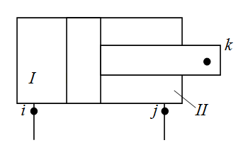
ПРИМЕЧАНИЕ: Pilot operated check valve has two moving parts(see Fig.): valve (nodes i, j, k) and pusher (nodes r, s, t).
                               Node r of pusher at the same time is a node i of valve.


The valve structural parameters


Physical, geometrical and design parameters of the valve

No

Nodes numbers


Mass
of
moving
part


kg
Working
area
from
pressure
line
(node i)
cm2
Working
area
from
drain
line
(node j)
cm2
Dry
friction
force


N
Maximal
stroke
of
moving
part

mm
Prelim.
comp-
ression
of
spring

mm
Coeff.of
viscous
friction


N.s/m
Rigi-
dity
of
spring


N/m
Average
diam.
of throt-
tling
crack

mm
Flow
coeff.
of throt-
tling
crack
-
Angle
of the
valve
cone


deg
i j k

The pusher structural parameters


Physical, geometrical and design parameters of the pusher

No

Nodes numbers


Mass of
moving
part


kg
Working
area
from
pressure
line
(node r)
cm2
Working
area
from
drain
line
(node s)
cm2
Dry
friction
force


N
Maximal
stroke of
moving
part


mm
Initial
clearance


mm
r s t


L i n e a r    d y n a m i c    l i n k s    of    c o n t r o l    s y s t e m s

Number of links (to 15)


The link structural parameters


Coefficients of the link equation


No
Nodes numbers

a0
a1
a2
b0
b1
c0
c1
d0
e0
i

j

k

The equation coefficients for different types of linear dynamic elements


The 2-th order links


The 1-th order links


The 0-th order links

   1. General case:    a2 ≠ 0.
   2. Aperiodic (oscillatory):
       a2 ≠ 0, b1 = c1 = 0.
   3. Inertial integrating:
       a2 ≠ 0, a0 = b1 = c1 = 0.
   1. Aperiodic (inertial)
       a1 ≠ 0, a2 = b1 = c1 = 0.
   2. Perfect integrating:
       a1 ≠ 0, a0 = a2 = b1 = c1 = 0.
   3. Inertial differentiating:
       a1 ≠ 0, a2 = b0 = c0 = 0.
   1. Perfect amplifier
       (instantaneous), an adder:
       a0 ≠ 0, a1 = a2 = 0.
   2. Perfect differentiating:
       a0 ≠ 0, a1 = a2 = b0 = c0 = 0.
   3. Perfect with introduction of derivative:
       a0 ≠ 0, a1 = a2 = c0 = 0.


W h e e l    m o v e r

Number of wheels (axles) (to 8)

NOTES:
1. This element is either a wheel with independent drive, or the drive axle.
2. Side scheme of transmission is replaced by the equivalent two-wheel scheme with independent drive of wheels.
3. The moment of inertia is given to the shaft of the wheel motor (axis, side) and is shown in the table of motor's data.


The wheel structural parameters


Physical, geometrical and design parameters of the wheel

No

Nodes numbers

Gear
ratio


-
Efficiency
of gear


-
Free
radius
of the
wheel

m
Vertical
axle
(wheel)
load

N
Radial
stiffness
of tire


N/m
Circum-
ferential
stiffness
of tire

N/m
Rolling
resistance
coeff.


-
i j k
К р и в а я    б у к с о в а н и я    к о л е с а    δ ( R ).
R - окружное усилие на колесе, Н;    δ - относительное буксование, безразмерно.

R1 R2 R3 R4 R5 R6 R7 R8 R9 R10
δ1 δ2 δ3 δ4 δ5 δ6 δ7 δ8 δ9 δ10

The wheel structural parameters


Physical, geometrical and design parameters of the wheel

No

Nodes numbers

Gear
ratio


-
Efficiency
of gear


-
Free
radius
of the
wheel

m
Vertical
axle
(wheel)
load

N
Radial
stiffness
of tire


N/m
Circum-
ferential
stiffness
of tire

N/m
Rolling
resistance
coeff.


-
i j k
W h e e l    s l i p p i n g    c u r v e    δ ( R ).
R - circumferential force on the wheel, N;    δ - relative slipping, dimensionless.

R1 R2 R3 R4 R5 R6 R7 R8 R9 R10
δ1 δ2 δ3 δ4 δ5 δ6 δ7 δ8 δ9 δ10


D i e s e l s

Number of diesels (to 2)


The diesel structural parameters


Physical, geometrical and design parameters of the diesel

No

Nodes numbers


Inertia
moment
of
rotating
details


kg.m2
Torque
increment
at maximal
fuel
supply

N.m
Coeff.of
viscous
friction
in
diesel
regulator

N.s/m
Coefficients of diesel regulator setting


Gear
ratio
of
regulator
drive


-
Rigidity
of
regulator
spring


N/m
Force of
regulator
spring
prelim.
compres-
sion

N
Maximal
stroke
of
regulator
muff


mm

i

j

k
ke

N
b

N.s2
k

N.s2/m
The    d i e s e l    c h a r a c t e r i s t i c    Мe ( ωj ).
ωj - an angular velocity of the diesel shaft (in node j ), rad/s;    Мe - the diesel shaft torque, N.m .

ω1 ω2 ω3 ω4 ω5 ω6 ω7 ω8 ω9 ω10
M1 M2 M3 M4 M5 M6 M7 M8 M9 M10


D i r e c t i o n a l    c o n t r o l    v a l v e s

Number of DCV spools (to 5)

NOTE: The order of the nodes (input-output) must correspond to the direction of flow. 
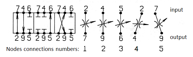
Positions of the spool, determining the field of the open connection

The DCV spool structural parameters


Physical, geometrical and design parameters of the spool

No
Numbers of connections of the nodes / Numbers of nodes on the input and output connections


Condi-
tional
pass
dia-
meter
mm
Max
spool
stroke


mm
Coeff.
of the
spool
channels
flow
-
1 2 3 4 5 6
input output input output input output input output input output input output

Positions of the spool determining areas of opening of ports 1 - 6, mm

1 2 3 4 5 6
z1 z2 z3 z4 z1 z2 z3 z4 z1 z2 z3 z4 z1 z2 z3 z4 z1 z2 z3 z4 z1 z2 z3 z4


P a r a m e t e r s    of    the    v e h i c l e    m o t i o n


Vehicle mass, kg Resistance to the vehicle movement, N Longitudinal road slope, deg.


C o n s t a n t    e x t e r n a l    l o a d s

Load torques of mechanisms, N.m in order of numbers of hydraulic motors
Forces on the cylinders rods, N      in order of numbers of hydraulic cylinders


E x t e r n a l    p e r t u r b a t i o n s    and    c o n t r o l    s i g n a l s

Number of perturbations (to 10)


   Type of perturbation TP:

     1 - load torque given to the N-th motor shaft, N.cm;
     2 - force on the N-th cylinder rod, N;
     3 - relative displacement of the N-th pump;
     4 - relative displacement of the N-th motor;
     5 - relative area of passage section of the N-th throttle;
     6 - displacement of the N-th spool, mm;
     7 - mass reduced to the N-th cylinder rod, kg;
     8 - resistance force of vehicle, N;
     9 - flow in the node N (static characteristic of valve Q(p), pump flow etc.), l/min.
     10 - control signal at the node N (voltage, V; current, mА; etc.)

     N - element type number if TP = 1 , . . . , 7 ;
     N = 0, if TP = 8;
     N - node number ifTP = 9 or 10


   Type of argument ТA (phase variable in the node NN):

     0 - time, s;
     1 - pressure, MPa;
     2 - flow, l/min;
     3 - force, N;
     4 - linear velocity, m/s;
     5 - torque, N.m;
     6 - angular velocity, rad/s;
     7 - linear displacement, mm;
     8 - rotation angle, rad.;
     9 - wheel slipping;
     10 - signal of control system (current, mA; voltage, V; etc.)

     NN = 0, if ТA = 0

Perturbation No 1

Type of
perturbation

TV
Number of
element type
or node
N
Type of
argument

ТА
Number of
node

NN
F u n c t i o n    of    e x t e r n a l    p e r t u r b a t i o n    y ( x ).
xi - the i-th value of the argument    yi - the i-th value of the function.

x1 x2 x3 x4 x5 x6 x7 x8 x9 x10
y1 y2 y3 y4 y5 y6 y7 y8 y9 y10

Perturbation No 2

Type of
perturbation

TV
Number of
element type
or node
N
Type of
argument

ТА
Number of
node

NN
F u n c t i o n    of    e x t e r n a l    p e r t u r b a t i o n    y ( x ).
xi - the i-th value of the argument    yi - the i-th value of the function.

x1 x2 x3 x4 x5 x6 x7 x8 x9 x10
y1 y2 y3 y4 y5 y6 y7 y8 y9 y10

Perturbation No 3

Type of
perturbation

TV
Number of
element type
or node
N
Type of
argument

ТА
Number of
node

NN
F u n c t i o n    of    e x t e r n a l    p e r t u r b a t i o n    y ( x ).
xi - the i-th value of the argument    yi - the i-th value of the function.

x1 x2 x3 x4 x5 x6 x7 x8 x9 x10
y1 y2 y3 y4 y5 y6 y7 y8 y9 y10

Perturbation No 4

Type of
perturbation

TV
Number of
element type
or node
N
Type of
argument

ТА
Number of
node

NN
F u n c t i o n    of    e x t e r n a l    p e r t u r b a t i o n    y ( x ).
xi - the i-th value of the argument    yi - the i-th value of the function.

x1 x2 x3 x4 x5 x6 x7 x8 x9 x10
y1 y2 y3 y4 y5 y6 y7 y8 y9 y10

Perturbation No 5

Type of
perturbation

TV
Number of
element type
or node
N
Type of
argument

ТА
Number of
node

NN
F u n c t i o n    of    e x t e r n a l    p e r t u r b a t i o n    y ( x ).
xi - the i-th value of the argument    yi - the i-th value of the function.

x1 x2 x3 x4 x5 x6 x7 x8 x9 x10
y1 y2 y3 y4 y5 y6 y7 y8 y9 y10

Perturbation No 6

Type of
perturbation

TV
Number of
element type
or node
N
Type of
argument

ТА
Number of
node

NN
F u n c t i o n    of    e x t e r n a l    p e r t u r b a t i o n    y ( x ).
xi - the i-th value of the argument    yi - the i-th value of the function.

x1 x2 x3 x4 x5 x6 x7 x8 x9 x10
y1 y2 y3 y4 y5 y6 y7 y8 y9 y10

Perturbation No 7

Type of
perturbation

TV
Number of
element type
or node
N
Type of
argument

ТА
Number of
node

NN
F u n c t i o n    of    e x t e r n a l    p e r t u r b a t i o n    y ( x ).
xi - the i-th value of the argument    yi - the i-th value of the function.

x1 x2 x3 x4 x5 x6 x7 x8 x9 x10
y1 y2 y3 y4 y5 y6 y7 y8 y9 y10

Perturbation No 8

Type of
perturbation

TV
Number of
element type
or node
N
Type of
argument

ТА
Number of
node

NN
F u n c t i o n    of    e x t e r n a l    p e r t u r b a t i o n    y ( x ).
xi - the i-th value of the argument    yi - the i-th value of the function.

x1 x2 x3 x4 x5 x6 x7 x8 x9 x10
y1 y2 y3 y4 y5 y6 y7 y8 y9 y10

Perturbation No 9

Type of
perturbation

TV
Number of
element type
or node
N
Type of
argument

ТА
Number of
node

NN
F u n c t i o n    of    e x t e r n a l    p e r t u r b a t i o n    y ( x ).
xi - the i-th value of the argument    yi - the i-th value of the function.

x1 x2 x3 x4 x5 x6 x7 x8 x9 x10
y1 y2 y3 y4 y5 y6 y7 y8 y9 y10

Perturbation No 10

Type of
perturbation

TV
Number of
element type
or node
N
Type of
argument

ТА
Number of
node

NN
F u n c t i o n    of    e x t e r n a l    p e r t u r b a t i o n    y ( x ).
xi - the i-th value of the argument    yi - the i-th value of the function.

x1 x2 x3 x4 x5 x6 x7 x8 x9 x10
y1 y2 y3 y4 y5 y6 y7 y8 y9 y10


P a r a m e t e r s    for    c a l c u l a t i o n


Integration step h, s - recommended value 0.0001 s
Initial time, s
Number of integration steps
Step of the results output Н, s Н - multiples of h
Carrier of initial conditions (IC) 0 - zero IC, 1 - IC are entered on the screen(see below), 2 - IC in a special file

I n i t i a l    c o n d i t i o n s


NOTE.  Initial conditions have the following structure: node number - "force" - "speed" - "displacement",
            where "force" - pressure (MPa), force (N) or torque (N. m); "speed" - flow (l/min), linear (cm/s) or angular (rad/s) speed,
            "displacement" - linear displacement (cm), rotation angle (rad) or slipping (-).

     1      2      3
     4      5      6
     7      8      9
   10    11    12
   13    14    15
   16    17    18
   19    20    21
   22    23    24
   25    26    27
   28    29    30
   31    32    33
   34    35    36
   37    38    39
   40    41    42
   43    44    45
   46    47    48
   49    50    51
   52    53    54
   55    56    57
   58    59    60


What    the    c i r c u i t    n o d e s    the    c a l c u l a t i o n    r e s u l t s    are    d i s p l a y e d

List of the circuit nodes numbers

NOTE:
List of the circuit nodes, in which the results set displays in ascending order of node numbers.
If necessary to output all nodes of the circuit, put 0 instead of the list or at the beginning (in this case the list is ignored).
If necessary to output not in all nodes, but in the given nodes, you can specify the list of these nodes, and 0 is not assigned.